The one-million-kilowatt nuclear island steam generator is a first-line pressure vessel, which must withstand 15.4MPa high-pressure water during operation. For the first-grade safety bearing equipment, the uneven wall thickness will cause uneven stress on the parts under pressure, resulting in serious Hidden accidents. This paper mainly studies how to realize the process of normal wall thickness machining at any point on the inner and outer surfaces of the elliptical upper part.
First, the geometric characteristics of parts and accuracy requirements analysis
Part geometry
The part is a top-and-bottom shaped structure, the upper part is a combination of a cylinder and a conical surface, and the lower part is a sphere-like surface. The internal surface pattern size of the sphere has been given elliptical characteristics; the outer surface is connected to the R125mm arc surface, and then the inner surface is required to form a wall thickness to be equal to not less than 98 mm (see Figure 1).

Figure 1 upper head
2. Analysis of geometric accuracy requirements of parts
Overall, the part size tolerance is 3mm. The surface roughness value R a=3.2 μm should be in the range of economic accuracy for CNC precision machine tools. However, the surface of the sphere is required to be kept equal in thickness, and the problem becomes less complicated. From the smallest 98mm size, only the minimum physical boundary constraints of the part are given. According to GB/T1804-2000 medium M grade, the linear dimension limit deviation is ±0.3mm. That is to say, the accuracy of the wall thickness at any point on the inner and outer surfaces, according to the minimum size from 98mm to the minimum 110mm, the wall thickness tolerance and the variation range of the deviation should be within 0.6mm and the deviation within ±0.3mm. From the accuracy analysis, it can be seen that the difficulty in manufacturing is how to control the tolerance and accuracy of the spherical body wall thickness. The key point is how to distribute and control the tolerance distribution value of the machining system.
Second, the main error items and control measures of the process system
This geometrical accuracy and tolerance requirements are a relatively inconvenient process problem for large spherical parts with a combination of shaped bodies.
There are many factors affecting the wall thickness tolerance dimension in the process system, including tool system error term, machining process and method error term, and numerical control machining mathematical model comprehensive error term.
1. Influence of tool system error on surface equal thickness accuracy and measures
This part is a rotary part, suitable for vertical double column or vertical single column CNC vertical car with rotary table. Therefore, the comprehensive error of the machining system mainly includes the precision error of the rotary table of the machine tool, the linear motion trajectory of the vertical tool holder and the geometric position accuracy error of the table, the positioning and repeat positioning accuracy, the rigidity of the tool and equipment system, and the thermal deformation of the plastic material by the cutting heat. These factors will affect the accuracy of the inner and outer curved surface contours, occupy wall thickness tolerances, and narrow the actual tolerance variable space value. The integrated narrowing value target is assigned T/5 (see Figure 2).

Figure 2 Schematic diagram of machining system tolerance distribution
Equipment accuracy adjustment: target factory accuracy, considering the adjustment of the actual difficulty allows adjustment: worktable rotation accuracy of 0. 0 5mm / 360 °; tool holder verticality of 0.03mm / 1 000mm; positioning and repeat positioning accuracy of 0.015mm / 1 000mm. The table beating is fixed by the pad component and eliminates the error of the positioning surface. The plastic material is cooled by the cutting heat to reduce the heat accumulation of the cutting heat. Before the final finishing, the clamping component is loosened once and re-solidified with appropriate force; The equipment moves the sub-gap, enlarges the tool section and meets the processing range of the appropriate moving parts overhang to improve the system stiffness. The integrated error is controlled to 0.6/5=0.12mm with a deviation of ±0.06mm (see Figure 2). It should be understood that this project has strong controllability, but the error source is basically principled, so the error has incompressible rigidity.
2. Influence of processing technology and method on surface thickness accuracy and measures
The CNC machining process of this part is mainly manifested in the realization of the coincidence degree of the positioning reference between the stations and the ability to keep the original positioning intact during the machining process. For such large-size gaps, the finishing of the profiled body is precisely the weakness of the coincidence of the positioning reference and the stability of the positioning. It is reflected in two aspects: First, two working stations must be used to machine the inner and outer contour surfaces of the parts (see Figure 3, two working position positioning diagrams). At the first position, the positioning stability is good, the design basis and the process reference are easy to achieve uniformity and coincidence, and the positioning error is small. In the final finishing of the external curved surface, the geometric precision and the dimensional accuracy of the pattern and the technical requirements are easily realized. Station 2, because the center of gravity is too high, the positioning surface is too small, the positioning stability is poor, and the center axis of the calibration part is coaxial with the equipment turntable and the coincidence degree is poor. It can also be destroyed during clamping and force application and dynamic cutting. The original positioning trend. As a result, the thickness of the curved surface is uneven, and the wall thickness tolerance is also occupied, so that the actual tolerance variable space value is narrowed. The integrated narrowing value target is assigned T/4 (see Figure 2).

Figure 3 Two station positioning instructions
This technical error is a non-principle error. Non-principle errors have direct causal relationships with different methods and methods. For example, the selection of the positioning reference; the number of degrees of freedom, direction, purpose; positioning component processing; cutting parameter selection; clamping unit clamping mode, force direction direction point selection, etc., can derive different results. This paper assigns the T/4 error target, and the integrated error is controlled at 0.6/4=0.15mm with a deviation of ±0.075mm (see Figure 2). This is based on the maximum amount of variation in the process of processing according to a reasonable process, but the actual degree of conformity is considered when the probability of "false coincidence" is considered. For example, due to the asymmetry of the clamping force or the position of the applied point, the dynamic re-equilibration demand causes the original positioning reference to deviate; the external force of the demodulating part causes the part mounting surface to be incomplete contact with the positioning reference surface to affect the center axis of the part. Any inclination or the like.
According to the error item, the tolerance area and the tolerance width are appropriately divided within the tolerance range, and the control methods and means are studied on this basis.
Through research and implementation, this paper confirms the technical adjustment of these errors before the final finishing. The specific method and means are as follows: the machining of the inner and outer surfaces of the part must be divided into two stations (see Figure 3).

Fig. 4 Non-zero error analysis of the axis deflection deflection concentric correction
The final finishing is worthy of extrapolation before or after the inside and outside. It can be seen from Fig. 3 that the station has a low center of gravity; the positioning stability of the smoothing large plane is good; the rollover of the moving parts during calibration is small and convenient. Once accurately positioned, the axis of the part remains in line with the axis of the rotary machine tool, and the positioning stability is strong under dynamic conditions. Conversely, station 2 has a high center of gravity; the positioning stability of the smoothing facets is poor; the upper and lower parts must be moved during the adjustment, and the parts are highly roll-over; the upper and lower clamping forces are easily inconsistent, which tends to cause poor positioning of the bottom, and the part axis remains and the rotary machine tool The parallelism of the axis meets the accuracy difference, and there is a trend of rebalance demand in the dynamic environment. In particular, it is required that such an axis does not match and two error conditions occur. An error situation: see Figure 4 gives the deflection angle α, assuming that the ideal axis intersects the O at the positioning surface, then the tangential variation e = h tanα, h = 1 when the point is selected in the column h region; Coaxiality error = 2e; when α is small, the value of e is small. Assuming that the distribution tolerance is 1/2 given to the error element, the reflectance of the dial gauge concentricity is 0.075mm, α=arctan0.037 5 ? 2.15 °. However, the arbitrary cut angle β reflected by the spherical surface will be amplified by a large ratio, and the normal error δi will follow the amplification at any point, δi=sinβ, β=nα (n≥1, 0° <β<90°). As a result, the coaxiality error is acceptable, and the ball wall thickness error may be even worse. The second error case (see Figure 5): When the table value is 0, the oblique axis intersects the O' point. Since H/h=1673, the axis eccentricity e = h tanα, the result will be different inner and outer surfaces (ball) The error reflected from the shadow genitals is far beyond the scope.

Figure 5 Axis deflection concentric circle correction value is zero error analysis
Obviously, the first external and the inner method, even if the overall processing error of the shape processing is close to zero value, if the internal processing tends to be post, it is difficult to ensure the wall thickness and other wall precision, and the control is difficult. The key to the process technology problem is how to adjust the order of step one and step two. Imagine if you are machining a hollow circular shaft with a simple structure to ensure that the hole is coaxial with the outer circle so that the wall thickness is within a given accuracy range. The principle is to ensure the finishing of the largest physical size, the fine axis reference formed by the finishing of the inner hole, as a fine reference for machining the outer circle, so that the design basis and the process reference are both coincident and uniform.
From this principle, we can recognize that the part is inside and outside, and can ignore the error of the internal processing station to achieve the purpose of reducing the error. The ideal station sequence is shown in Figure 6.

Figure 6 Finishing ideal station
3. The definition of mathematical model of numerical control machining and its influence on the thickness accuracy of curved surface and measures
(1) Mathematical model definition of NC machining: From the geometric analysis of parts, the internal surface can be according to the elliptical mathematical model y=(b /a)a2-x2, then is the external ellipse? Assuming a wall thickness constant C, the concentric outer ellipse mathematical model is Y = (B / A) A2 - X2, where A = a + c, B = b + c; this process allows the inner and outer ellipse to have their respective contours The contours of the curve can be machined according to their respective mathematical equations. However, the problem is that the two curves are divided into two mathematical equations, because a≠b; there is b/a=m, m≠1; and it is revealed as non-circular. Since A≠a, B≠b; there are B/A=M, M≠m; revealing that the ellipse with different parameters has different ellipticities, so that the ellipticity changes on the inner and outer elliptic curves are inconsistent, resulting in unequal walls. The calculation results show that the wall thickness is 102mm (taken from the range of 98 to 110mm), that is, the constant C=102. As a result, the wall thickness error of the part can reach 7.22mm, which is far beyond the technical tolerance boundary in the pattern. Obviously, the outer part should not be elliptical. . According to the principle of equality at the normal thickness of any mass point at the baseline (see Figure 7), the external curve must be a spline curve to achieve the equivalent feature of the part.

Figure 7 isometric diagram
(2) Spline curve and high order insertion measures:
Based on the inner ellipse to generate equal-thickness spline curves, the curve precision is improved by point insertion. From the third-order spline curve to the 25th order, the insertion density is greatly improved, which is beneficial to improve the accuracy of the contour surface and further equalize the wall thickness (see Figures 8 and 9).
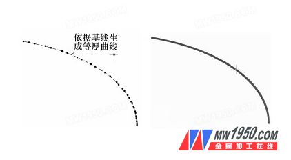
Figure 8 Third-order spline curve Figure 9 High-order sub-interpolation spline curve
Third, the conclusion
(1) Reasonable analysis and control of tool system error, machining process and method error, and three factors of numerical control machining mathematical model are the key technical issues that determine the qualified and stable quality of the elliptical head. It is the guiding process plan and process specification. Design rationality of the process orientation. The rigidity of the tool system error is truly reflected in the final accuracy of the part, but it has constant controllability. The machining process and method error have arbitrarily variable variability, but a reasonable process can eliminate the error source and make the theoretical error value zero.
(2) Mathematical model of NC machining, through principle analysis, model definition, under the premise of satisfying the servo system's ability to perform pulse equivalence, the outer surface passes the spline curve dense point, and the inner ellipse y=(b /a)a2-x2 reduces the variable The step size δX=X i-X i-1 is the dense point method, which greatly reduces the influence of the precision error value to zero.
(3) At present, this process has been successfully applied to the manufacture of the first domestic CPR1000 evaporator in China, and has been applied to a total of 6 steam generators for localized manufacturing. The processed parts meet the delivery technical parameters and standard specifications. The control of thickness precision and stability is within 0.15mm, and the research on the process method of this subject has been proved to be successful.
Lock Body,Door Lock Body,Zinc Alloy Mortise Lock,Mortise Sliding Door Lock Body
Wenzhou Shenghong Metal Products Co.,Ltd , https://www.shenghonglock.com