0 Preface
Bolted joints are widely used in aircraft, automobiles, various machinery and structures, and are the most basic connection methods in various mechanical equipment and structural parts. Bolt looseness caused by vibration is the main form of bolt failure. The main reasons for the loosening of the bolts under vibration are Pai and Hess [1 - 2], Izumi [3] and Koch [4], who believe that the sliding of the threads and nuts causes the bolts to loosen. Jiang et al. [5-6] studied bolt loosening caused by plastic deformation of the root of the thread. Friction is the key factor for the bolt to maintain the tightening state. The friction affects the tightening torque of the threaded engagement surface and the bearing surface of the nut, which in turn affects the pre-tightening force caused by the axial strain caused by the tightening torque. When the nut is tightened to the bolt When it is on, it is the action of friction that prevents the nut from rotating loose. Although friction is a fundamental factor in the bolt's anti-looseness, there is no definitive study on the bolt friction change of the joint under vibration. Therefore, the bolt preloading relaxation test under the resonance state is used to study the loosening process of the bolt. The scanning electron microscopy topography of the threaded meshing surface is used to analyze the influence of the friction coefficient on the loosening process and the microscopic causes of the friction coefficient change.
1 Vibration relaxation experiment
The test piece used in the test was two rectangular steel slabs of 45 gauge superimposed on the top and bottom, with thicknesses of 8 mm and 3 mm respectively. The test pieces of the joint plate were connected by single row bolts (Fig. 1), and the bolts were ordinary M5 bolts.

The vibration test system (Figure 2) mainly includes the excitation system, control system and acquisition system. The excitation system equipment is mainly a vibration table; the control system equipment includes a vibration table control system, a power amplifier; the acquisition system equipment includes a dynamic strain collector, a resistance strain gauge and a piezoelectric acceleration sensor. Fix one end of the test connection plate to the vibration table with a clamp, and add a weight to the other end. The experiment is divided into sine sweep and sine constant frequency experiments. The sweep frequency range is from 5 Hz to 500 Hz and the sweep duration is 3 min. The main purpose of the sweep test is to measure the resonant frequency of the bolted joint structure, and then
The sinusoidal fixed frequency vibration is applied to the bolted structural member by the natural frequency, and the sinusoidal fixed frequency test measurement data is the axial force of the bolt. The displacement of the sinusoidal vibration is set to 3 mm, the frequency is the resonance frequency, and the machine is stopped every 10 minutes during the experiment, the data is sorted and stored, the test piece is inspected for damage, and the pre-tightening force change data is stored and stored.

The load cell is designed to measure the axial force of the bolt. The force sensor is composed of a hollow cylinder and a strain gauge. The height and thickness of the hollow cylinder are designed according to the Saint-Venant principle. The material used for the load cell is 45# steel. The sealant is sealed with a sealant to protect the insulation resistance of the strain gauge and the strain gauge is not damaged during the vibration test. Finally, the resistance strain gauge is connected to the dynamic strain collector, the test channel is checked, and the dynamic strain gauge is balanced and cleared to ensure that there is no zero drift of the collected data.
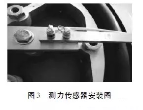
The load cell is installed between the nut and the connecting plate. The axial pre-tightening force of the bolt can be obtained by the force sensor, thereby achieving the purpose of detecting the pre-tightening force of the bolt. The load cell is installed as shown in FIG. Considering that the sensor is subjected to the axial pressure, the bending moment may occur due to the eccentric load, and the contact surface between the nut and the sensor will also generate a certain torque during the screwing process. The full bridge test method has a large bridge arm coefficient and can be eliminated. Due to the influence of the additional bending moment generated by the load eccentricity on the measured value, the bolt pre-tightening force is measured by the full bridge test method, and the pre-tightening procedure is adjusted according to the measured bolt pre-tightening force value.
2 Experimental results and analysis
2. 1 Preload change
The dynamic strain gauge collects the axial force change of the bolt, and the relaxation process of the bolt pre-tightening force under the vibration state can be seen. In Figure 4, the abscissa represents time and the ordinate represents preload. The prestressing stress range applied by the test is σp = (0.5 to 0.6) σs, which guarantees that in the elastic deformation stage, under the displacement vibration excitation, the bolt pre-tightening force remains basically unchanged at first, and starts to slowly decrease after 30 minutes. It shows that the bolt is loose, and it drops rapidly after 120 min. The slope of the curve becomes obviously larger. After 150 min, the curve changes gently, the pre-tightening force basically does not change, and the bolt has been loosened and failed. Compared with the previous test results [7], the preload force does not decrease from the beginning, but undergoes a period of smooth change, which is due to the difference in the preload force under the displacement load and the force load. The difference in this phase is mainly due to the difference in friction coefficient.
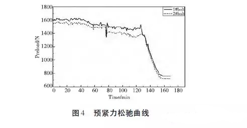
Under the action of vibration load, the change of bolt preload force is divided into four stages.
In the first stage, due to the increase of the friction coefficient, the spiral structure of the thread generates a relaxation torque. The relaxation torque generated by the shear force between the contact surfaces under the external load is balanced with the friction torque, and the bolt is not loose. This stage did not appear in the previous analysis of bolt preload tension relaxation analysis, because this experiment is to use the displacement loading vibration of the connecting structural member instead of the exciting force vibration, causing the shearing force of the loose bolt to be squeezed by the connecting plate. The deformation provides that the shear force changes are complex and the amplitude is small.
In the second stage, due to the decrease of the friction coefficient, the friction torque is not enough to overcome the relaxation torque, the bolt starts to loosen, the axial strain decreases, and the pre-tightening force of the bolt decreases slightly.
In the third stage, the thread pair can not meet the self-locking condition and the nut is rotated. The axial strain of the bolt is rapidly reduced, and the pre-tightening force is also drastically decreased.
The fourth stage bolt has been loosened and the preload is at a minimum. The bolts need to be tightened, otherwise the rigidity and tightness of the connecting parts will be affected, and the connecting parts will be separated and malfunction.
2. 2 Microscopic analysis of threaded meshing surface
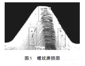
It can be seen from Fig. 5 that the threaded bevel produces abrasive debris and scratches under repeated grinding, and the surface is not smooth. The closer these regions are to the tip position, the more severe the wear. The deformation process caused by contact sliding will produce a slip zone. The movement of the slip zone may intersect with impurities to generate more dislocations. Micro-cracks will form at the place where the dislocations accumulate [8]. These have certain friction coefficients. influences.
There is no change in the pre-tightening force in the first stage. The thread is twisted and deformed under the contact force, especially the contact pressure at the tip of the tooth is the largest, and the deformation causes the surface to be slightly worn [9]. The wear damage of these thread contact surfaces leads to the contact surface. The increase in friction factor.
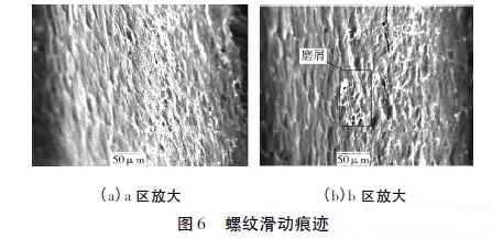
In the second stage, the surface of the thread is plastically deformed under contact pressure and sliding. The plastic deformation continuously accumulates, and the dislocation density of the subsurface increases continuously. Dislocation accumulation occurs. When dislocations meet some defects, holes are formed. As the sliding continues, the local part will undergo intense cooling and hardening, the material will become very brittle, and the grinding particles will be generated during the sliding process of the contact surface, usually called the third body, which can be seen in Figure 6. It is seen that many cracks are generated on the surface of the scratched strip. These microcracks are pressed, shredded and gradually penetrated, and the surface will fall off in a granular form. The effect of the abrasive scrap is to accelerate the surface damage as an abrasive, and to separate the two surfaces. Reducing contact, the appearance of the third body causes a decrease in the coefficient of friction.
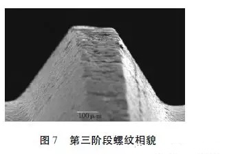
The third stage of sliding produces a large amount of abrasive debris and is trapped between the surface of the thread. The surface material rubs against the abrasive particles. The abrasive particles "polish" the rough surface and the contact surface becomes smooth (Figure 7), making the bolt friction coefficient reduce.
The friction factor of the fourth stage is reduced to a minimum and remains unchanged.
Based on the above analysis, the friction coefficient has experienced a process of first increasing, then decreasing slowly, and rapidly decreasing until it reaches the lowest value. The friction factor is closely related to the loosening process, and the change of the friction coefficient is controlled for the bolt. It is important to use lubricants during the tightening process to reduce the sliding wear on the contact surfaces. The different changes of friction coefficient are determined by the surface wear condition. The finite element analysis model is established by bolted joints, and the causes of wear at the threads are analyzed to study the change of friction coefficient.
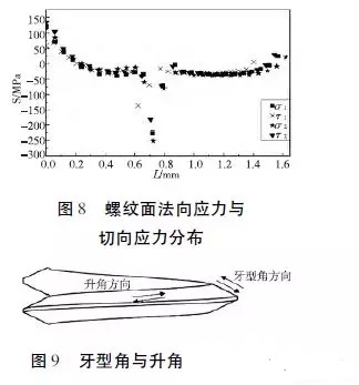
2. 3 finite element calculation of the meshing surface
The contact pressure and shear force of the thread surface were obtained by finite element analysis software. The sliding of the bolt contact surface and the distribution of the normal stress of the contact surface are related to the distribution of the tangential stress. The normal stress affects the friction force and the tangential stress affects the sliding. The profile angle of the thread is 60°, and the normal stress σ1 and the shear stress τ1 in the angular direction of the thread on the inclined surface of the thread are distributed along the inclined surface of the thread. The rising angle of the thread is 3.25°, the normal stress of the inclined surface of the spiral angle is σ2, and the shear stress is τ2. At the tip position of the thread, it is subjected to large pressure and shearing force. The pressure causes plastic deformation of the tooth tip position, and the shearing force causes mutual sliding. Under the plastic deformation and sliding action, the tooth tip position shows signs of severe wear. Obvious wear and cracks can also be seen from the SEM image (Fig. 5). The difference in wear causes different coefficients of friction.
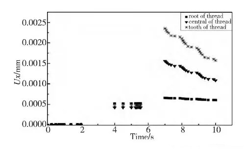
The curve in Figure 10 represents the lateral sliding displacement at the root, middle and tip of a thread, with a preload applied in 4 to 6 s and a displacement of 3 mm in 7 to 10 s. It can be seen that the sliding of the thread surface mainly occurs at the tooth tip position and the middle portion of the thread surface, and the root of the thread is elastically deformed, so that the lateral sliding displacement thereof is not large at the other two places. This also explains the obvious sliding wear of the middle of the thread surface and the tip of the thread in the thread profile of the scanning electron microscope (Fig. 6). Under the action of pressure and sliding, the position of the tooth tip is seriously damaged, and a large amount of abrasive particles are generated. The fatigue crack in the middle of the thread is initiated and expanded, and these factors all lead to a decrease in the friction coefficient.
3 Conclusion
In this paper, the loosening behavior of bolts under resonance is studied. The conclusions are as follows:
1) In the initial stage of displacement vibration, the bolt pre-tightening force does not drop directly, but undergoes a period of smooth change. This process is due to the increase of the friction coefficient without slack.
2) Based on the results of finite element analysis on the contact force distribution and relative sliding analysis of the threaded contact surface, combined with the scanning electron microscope topography of the thread, it is found that the tip position is subjected to the maximum pressure; the sliding phenomenon in the middle and the tip position is obvious, under pressure The deformation and sliding cause the surface wear of these two places to increase.
3) Different changes in the friction factor caused by the different degrees of wear divide the loosening process into four different stages. In the first stage, the slight abrasion damage causes the surface friction factor to increase. In the second stage, the microcrack penetration causes the material to fall off and the wear debris to be generated, and the wear debris causes the friction factor to decrease. In the third stage, the contact surface intercepts a large amount of wear debris. The wear debris has a "polish" effect on the rough surface, and the contact surface becomes smooth, so the friction factor drops rapidly. In the fourth stage, the friction factor is reduced to a minimum and the bolts are completely loose.
References
[1] PAI NG, HESS DP. Experimental study of loosening of threaded fastener due to dynamic shear loads [J]. Journal of Sound & Vibration, 2002, 253 (3) : 585 - 602.
[2] PAI NG, HESS DP. Three - dimensional finite element analysis of threaded fastener loosening due to dynamicshear load [J]. Engineering failure analysis, 2002, 9(4): 383-402.
[3] IZUMI S, YOKOYAMA T, IWASAKI A, S SAKAI. Three-dimensional finite element analysis of tightening andloosening mechanism of threaded fastener [J]. Engineeringfailure analysis, 2005, 12( 4) : 604 - 615.
[4] KOCH D, FRIEDRICH C, DINGGER G. Simulation of rotationalself - loosening of bolted joints[M]. Wiesbaden: Simulation of connections and joints in structures, 2010: 65 - 78.
[5] JIANG Y, ZHANG M, LEE CH. A study of early stageself - loosening of bolted joints [J]. Journal of Mechanical Design, 2003, 125 (3): 518 - 526.
[6] JIANG Y, ZHANG M and LEE CH. Finite element modelingof self - loosening of bolted joints [J]. Journal of Mechanical Design, 2007, 129 ( 2) : 218 - 226.
[7] Shan Changwei, Yang Qi, Wu Qing. The effect of vibration on the tightening effect of high-strength bolts [J]. Light Vehicle Technology, 2008( 9) : 23 - 26.
[8] Yu Hanqing, Chen Jinde. Metal plastic forming principle [M]. Beijing: Mechanical Industry Press, 1999.
[9] ECCLES W, SHERRING I, ARNELL R D. Frictional changes during repeated tightening of zinc plated threaded fasteners [J]. Tribology International, 2010, 43 (4): 700-707.
Whether you run a fast-paced restaurant or a cozy coffee shop, you know the importance of providing your guests with a sturdy place to eat their meals. With the Lancaster Table and Seating black Metal Table Base, you can create a balanced dining area for customers in your establishment.
These table bases is very affordable and great quality. It is easy to install and very sturdy. It doesn't scratch the floor when moved and is easy to clean.
Material is cast iron,stainless steel,aluminum.
Finished is black,chrome,brush,polished.


Table Base,Metal Table Base,Dining Table Base,Cast Iron Table Base
Foshan Nanhai Xin Jianwei Hardware Co., Ltd , http://www.aaghardware.com