Gear transmission is a widely used mechanism in mechanical systems, playing a critical role in power transfer. The precision of gear manufacturing and the accuracy of installation directly influence the performance and lifespan of the gears. In bevel gear systems, it's essential that the apexes of the conical gears align correctly, with the contact area between the teeth typically located slightly towards the smaller end of the tooth length. Under normal operating conditions, the contact pattern of well-aligned bevel gears is illustrated in Figure 1.

Figure 3: Cone Apex Angle Change (Contact at Large End)
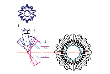
Figure 4: Reverse Delta Swing Angle (Contact at Small End)
1. Planetary Gear Shaft 2. Planetary Gear 3. Half Shaft Gear
When it comes to machining hyperbolic holes, traditional CNC lathes typically use X and Z-axis interpolation to create straight or tapered holes. However, they cannot produce non-circular profiles like hyperbolas without additional axes. To machine a hyperbolic hole, the Y-axis must be involved for proper interpolation. This makes it challenging for standard CNC lathes to achieve such complex shapes.
An alternative approach involves rotating a hyperbola around an imaginary axis to form a single-leaf hyperboloid. With the right programming, even a standard CNC lathe can generate a hyperbolic shape by interpolating the X and Z axes according to the hyperbolic equation.
The equation for a single-leaf hyperbola is:
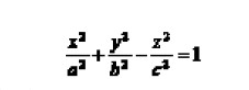 This equation represents the mathematical model of a hyperbolic bore. By knowing the length of the workpiece and the diameters at both ends, the coefficients A and B can be calculated. This leads to an equation where y corresponds to the X-axis on the lathe, and x corresponds to the Z-axis.
In practice, the smallest diameter of the hyperbolic inner bore occurs at the center of the hole, with a controlled difference of 0.05 to 0.1 mm between the two ends.
This equation represents the mathematical model of a hyperbolic bore. By knowing the length of the workpiece and the diameters at both ends, the coefficients A and B can be calculated. This leads to an equation where y corresponds to the X-axis on the lathe, and x corresponds to the Z-axis.
In practice, the smallest diameter of the hyperbolic inner bore occurs at the center of the hole, with a controlled difference of 0.05 to 0.1 mm between the two ends.

Figure 5
**Conclusion**
This paper outlines the background, mathematical modeling, and machining techniques for hyperbolic holes. The application of these holes allows for automatic adjustment of the internal bevel gear meshing in differentials. The concept of hyperbolic holes extends beyond bevel gears and is also applicable to cylindrical gears, making it a significant advancement in the broader field of gear technology. Its implementation holds great importance for improving efficiency, precision, and longevity in mechanical systems.

Figure 1: Schematic of Normal Contact Area

Figure 2: Cone Apex Translation (Partial Contact)
Figure 3: Cone Apex Angle Change (Contact at Large End)
Figure 4: Reverse Delta Swing Angle (Contact at Small End)
1. Planetary Gear Shaft 2. Planetary Gear 3. Half Shaft Gear
Figure 5
Electric Tamping Rammer,Plate Compactor C80t, Manual Vibrating Plate Compactor
Vibropac Machinery Co.,Ltd , https://www.vibropac-power.com