Gear transmission is one of the most widely used mechanisms in mechanical systems. The precision of gear manufacturing and installation directly impacts their meshing performance and overall service life. In bevel gear systems, it's crucial that the apexes of the cones align properly, ensuring that the contact area between the gears lies slightly toward the smaller end of the tooth length. Under normal operating conditions, the contact area of a well-matched pair of bevel gears is illustrated in Figure 1.
However, due to various factors such as machining inaccuracies or assembly errors, abnormal contact patterns can occur during gear meshing. For example, in a differential system, side gears interact with planetary gears. Because of unavoidable manufacturing and assembly tolerances in the planetary gear shaft and its housing, the alignment of the planetary gears may be affected. When the shaft experiences misalignment, three types of abnormal contact areas—shown in Figures 2, 3, and 4—can appear between the planetary gear and the side gear. These irregularities can significantly reduce the accuracy and lifespan of the gear system.
Figure 3: Cone apex angle δ (contact at the large end)
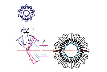
Figure 4: Reverse δ swing angle (contact at the small end)
1. Planetary gear shaft 2. Planetary gear 3. Half shaft gear
When it comes to machining hyperbolic holes, traditional CNC lathes typically use X and Z-axis interpolation to produce straight or tapered holes. However, they are not capable of creating non-circular profiles like hyperboloids. To machine a hyperbolic hole, Y-axis interpolation is required, which is generally not available on standard CNC lathes. Another approach involves rotating a hyperbola around an imaginary axis to form a single-leaf hyperboloid. By programming the X and Z axes according to the hyperbolic equation, a hyperbolic shape can be achieved even on a conventional lathe.
The mathematical model for a single-leaf hyperboloid is given by:
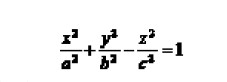 As shown in Figure 6, the hyperboloid bore schematic includes a mathematical representation where the length of the workpiece (L), and the diameters (φ₠and φ₂) of the two ends are used to determine coefficients A and B. This leads to an equation involving the Y-axis, where y corresponds to the X-axis of the lathe and x corresponds to the Z-axis.
In practical applications, the minimum diameter of the hyperbolic inner hole is located in the middle of the hole’s length, with a controlled difference between the two ends of about 0.05 to 0.1 mm.
As shown in Figure 6, the hyperboloid bore schematic includes a mathematical representation where the length of the workpiece (L), and the diameters (φ₠and φ₂) of the two ends are used to determine coefficients A and B. This leads to an equation involving the Y-axis, where y corresponds to the X-axis of the lathe and x corresponds to the Z-axis.
In practical applications, the minimum diameter of the hyperbolic inner hole is located in the middle of the hole’s length, with a controlled difference between the two ends of about 0.05 to 0.1 mm.

Figure 5
Conclusion:
This paper outlines the background, mathematical model, and machining techniques for hyperbolic holes. The implementation of hyperbolic holes allows for automatic adjustment of bevel gear meshing in differentials. Beyond bevel gears, this concept has also been applied to cylindrical gears, making it a significant advancement in the broader field of gear technology. The development of hyperbolic hole machining opens new possibilities for improving gear performance and durability across various mechanical systems.

Figure 1: Schematic diagram of normal contact area
However, due to various factors such as machining inaccuracies or assembly errors, abnormal contact patterns can occur during gear meshing. For example, in a differential system, side gears interact with planetary gears. Because of unavoidable manufacturing and assembly tolerances in the planetary gear shaft and its housing, the alignment of the planetary gears may be affected. When the shaft experiences misalignment, three types of abnormal contact areas—shown in Figures 2, 3, and 4—can appear between the planetary gear and the side gear. These irregularities can significantly reduce the accuracy and lifespan of the gear system.

Figure 2: Cone apex translation Δ (partial contact)
Figure 3: Cone apex angle δ (contact at the large end)
Figure 4: Reverse δ swing angle (contact at the small end)
1. Planetary gear shaft 2. Planetary gear 3. Half shaft gear
Figure 5
Vibropac Machinery Co.,Ltd , https://www.vibropac-power.com