China is located between the two most active seismic belts in the world. The eastern Pacific Rippling Earthquake Belt, the western and southwestern regions are the areas through which the Eurasian earthquake belt passes, and it is one of the countries in the world with multiple earthquakes. China's seismic activity is not only of high frequency, but also of high intensity, and the range of funds for earthquake activities is funded by the project: State Grid Corporation of Science and Technology (Study on Seismic Design Criteria of Power Transmission and Transformation Projects).
It is very extensive. 3. Since the 1960s, there have been 10 earthquakes in our country that have caused major damage to electrical equipment. In particular, on May 12, 2008, a magnitude 8.0 earthquake occurred in Wenchuan, Sichuan Province. Caused heavy losses. 2. Post-earthquake investigations revealed that the breakdown rate of electric ceramic high-voltage electrical equipment such as circuit breakers, surge arresters, disconnectors, transformers, etc. is very high, which is a major factor in the failure of substations; in addition, these damages are numerous and widely distributed. ,Various voltage levels, very typical. Electrical equipment damage caused by earthquakes mainly manifests as broken porcelain insulators, tilted or falling equipment.
At present, there are few seismic studies on electrical equipment in China. Therefore, it is of great practical significance to conduct vibration test and finite element analysis of electrical porcelain high-voltage electrical equipment.
1 Shaking table test study Through the full-scale true-type shaking table test of typical structures, the key parameters such as acceleration and strain in key parts of various models under different earthquakes were determined to determine the dynamic characteristics, seismic performance and equipment support of the structure itself. The mechanical performance of the upper equipment connection provides the correctness and rationality of the model for evaluating the seismic performance and structural design methods of the structure.
1.1 Selection of test objects In this test, 220 kV insulators and lightning arrester equipment with typical damage in the earthquake are selected. The insulators and lightning arresters used are all products used in actual projects. The test is a true test of foot size. The pillar insulator adopts the high-strength porcelain outdoor rod-type pillar insulator produced by the dry process, and the model is ZSW-252/10K-3, which is produced by Xi'an Xideng High Voltage Electric Porcelain Co., Ltd. 220kV zinc oxide surge arrester model is Y10W5-204/532W, produced by Xi'an West Electric Lightning Arrester Co., Ltd.
Insulator and arrester bracket structure adopts two different diameter steel tubes of 250mmX6mm and 300mmX6mm, respectively, so there are four test models: 1丫2-250,丫2-300,:8 units are suitable for the analysis of slender to medium stubby beams. The structure, which is based on the theory of Timken Beam Structure 6 and takes into account the effects of shear deformation. The 220kV surge arrester's finite element model was also used in a 220kV zinc oxide surge arrester of type Y10W5-204/532W produced by Xi'an Xidian Lightning Arrester Co., Ltd. As shown, the beam element Beaml 88 is displayed in the form of an entity with a total of 50 elements.
2.1 Computational model comparison verification, type VII, for other types; YS finite element program, computational analysis of seismic responses under different types of seismic action, both for the test results package can be thus proposed reasonable and effective finite element analysis model for this electrical facility The seismic performance was studied.
220kV lightning arrester finite element model 2.2 dynamic characteristics analysis of the maximum acceleration value of the EL-xntro wave to make adjustments. 220kV arrester bracket structure uses 250mmX6mm and 300mmX6mm two different diameters of steel pipe, so the model total lightning arrester bracket and the device at the top of the maximum absolute acceleration in Table 1, the arrester bottom of the porcelain casing root strain maximum in Table 2. Table are There are test comparison data.
Input waveform location calculation result Test result Calculation result Test result Acceleration/g Acceleration/g Magnification Acceleration/g Magnification Acceleration/g Magnification Acceleration/g Magnification coefficient Top of the bracket 0.0641 Table 2 Strain value of ceramic casing root Maximum input : Waveform bracket arrester arrester arrester Earthquake acceleration/g calculation results Test results Calculation results The test results are compared between the finite element calculation analysis and the test data. It is considered that the selected model and analysis method are reasonable, the obtained result is reliable, and the same can be applied to Other types of electrical equipment.
Through the comparison between the finite element calculation and the experimental results, it is found that there are errors, and the reasons for the analysis are as follows: First, since the finite element method is an approximate numerical analysis method, the precision of the model directly affects the accuracy of the results, and only the entire structure is considered. Reactions, so a certain simplification in the modeling, and the parameters of the various materials in the model are ideal material parameters, and may be different from the actual material in the test; Secondly, for each device, the shaking table can only be The test of one set of equipment has limitations in its universal significance. The defects in the production process, the uneven distribution of material properties, and the limitations of shaker test equipment conditions may cause deviations in the test results. There is an error with the finite element result.
A total of 220 prototypes of 220 kV pillar insulators, 220 kV lightning arresters, 500 kV circuit breakers, 750 kV arresters, and 750 kV voltage transformers with four voltage levels were used for the finite element analysis. The main calculation data of these devices are shown in Tables 3 to 4. The table contains the test comparison data.
Table 3 220kV insulator and arrester test and finite element data height/mass/kg vibration frequency/Hz dynamic amplification factor test equipment test stand equipment support equipment test finite element artificial wave mean value table 4 kV equipment finite element data equipment support height/ m equipment height / m stent mass / kg equipment quality / kg vibration frequency / Hz power amplification factor (EL ~ centro wave) 750kV transformer 750kV arrester 500kV circuit breaker calculated by finite element analysis, including 220kV insulator and arrester bracket diameter of 250mm At that time, the power amplification factor was larger than that of a stent with a diameter of 300 mm. The former was about 1.1 times that of the latter, which was basically consistent with the test results.
According to the provisions of the 50260-96 seismic code for power facilities, when only the electrical equipment body is subjected to seismic design, the bending moment, shear force and horizontal acceleration shall be multiplied by the dynamic response amplification factor of the support structure. For the electrical equipment installed outdoors, the equipment support The power amplification system can be found from the test data and finite element calculations. The 00kV circuit breaker, 750 kV arrester and transformer have low natural vibration frequency (0.86~1.58Hz). The weight of the equipment is large. The power amplification factor of the bracket is 2.26~2.49. There is a big difference between the values ​​of the recommendations and the specifications.
The self-resonant frequency of the kV insulator and arrester is relatively high (3.8~7.5Hz). The weight of the equipment is small. When the synthetic seismic wave is input according to the requirement in the specification 5.4.4, the dynamic amplification factor of the four test pieces is 23~1.56, which is larger than the specification. Values ​​1. and Taft waveforms, test and calculation of the power amplification factor of 1.25, and the provisions of the provisions of 5.2.6 1. 0 ~ 1.2 there is still a big gap.
Through analysis of the stress and strain of electrical equipment, it can be seen that the 220kV insulator and lightning arrester are basically in a safe state when the earthquake is 7~9 degrees. Comprehensive analysis of the data, it is recommended that the insulator bracket takes 6mm, the arrester bracket takes the 500kV circuit breaker, the 750kV arrester and the transformer in the 8 degree rare (0.4g) and above earthquake, the material is close to or exceed the yield limit state, the equipment There is a possibility of destruction.
3 Conclusion The anti-seismic performance of porcelain-electric high-voltage electrical equipment is poor, and the higher the voltage level, the more obvious. In high-intensity seismic regions, it is recommended to use tank-type cutting equipment to reduce the height of the equipment and improve the anti-seismic capacity.
Both true test and theoretical calculation show that the dynamic amplification factor of the bracket on the upper porcelain electric high-voltage electrical equipment fluctuates in a wide range, and is often much larger than 1. 2.GB50260-96 power installation seismic design code for equipment support dynamic amplification factor The regulations are too small. It is recommended that the brackets and the electrical equipment body be calculated as a whole.
Electric ceramic high-voltage electrical equipment is generally thin and high-brick ceramic pieces as insulating sleeves or load-bearing columns, poor bending performance. Increasing the strength of the porcelain casing and using shock absorption and vibration isolation measures on the basis can effectively improve its seismic performance.
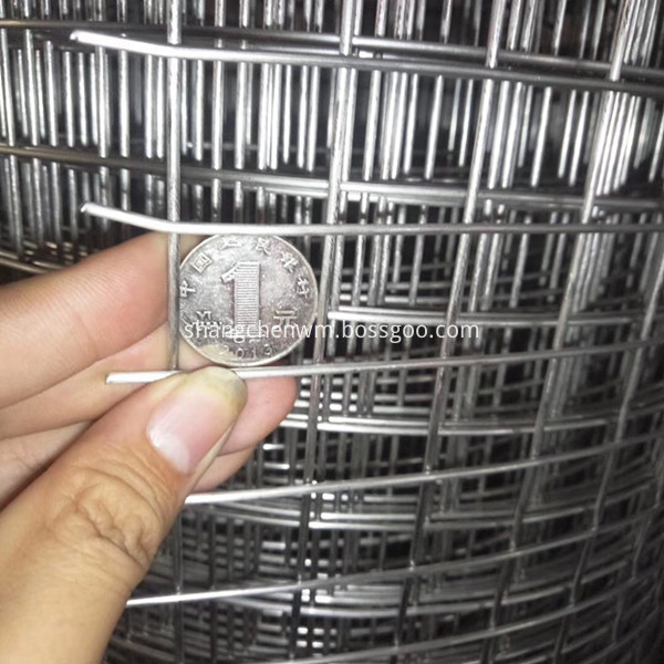
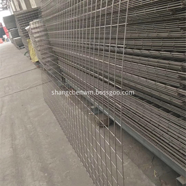
The welded wire mesh including high quality low carbon steel welded wire mesh, Stainless Steel Welded Wire Mesh, Galvanized Welded Wire Mesh, PVC welded wire mesh, etc.
Weaving type and characteristics: galvanizing before or after welding, hot-dipped, electro galvanizing, PVC coating. Strong corrosion-resisting and oxidation-resisting etc.
Usage of welded wire mesh: Widely used in industry, agriculture, building, transportation, mine, playground, lawn, cultivation, enclosure fence, decoration, machine protection, etc.


Welded Wire Mesh
Welded Wire Mesh,Galvanized Welded Wire Mesh,PVC Coated Welded Mesh,Stainless Steel Welded Mesh,Black Welded Wire Mesh,Stainless Steel Welded Wire Mesh,Welded Wire Mesh Sheet,Stainless Steel Wire Mesh Sheet
ANPING COUNTY SHANGCHEN WIREMESH PRODUCTS CO.,LTD , https://www.scfiltermesh.com